HOME → Dragon Plastic Model Kits → 1/350 Warships → 1021
Barcode: 0 89195 81021 2
Case Pack: 20 Pieces per case
Box Size: 7.9" x 15.7" x 2.6"
Features:
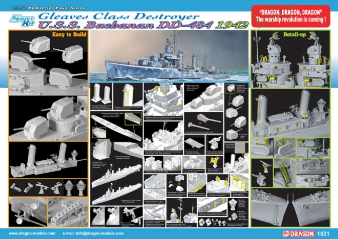
- One piece slide molded upper hull with undercut details realistically represented
- Waterline or full hull version can be assembled
- Sponsons are represented on lower hull by slide mold technology
- Rudder is movable
- True to scale ultra thin propellers reproduced
- Extra thin shield walls on superstructure reproduced for accurate 1/350 appearance
- Extra fine detail on superstructure walls like hose, ladder patterns delicately reproduced
- Extremely fine detailed parts like davits for whalers
- Whalers with photo etched parts finely reporduced
- Finest tread pattern ever reproduced
- Funnels provided with option of molded on ladders or add on photo etched ladders
- 12 inch, 24 inch and 36 inch searchlights provided
- 36 inch searchlight platform delicately rendered
- Movable structure for 36 inch searchlight with clear part included
- Special device included to bend specific photo etched parts to correct angle
- Realistically detailed gun barrels are slide molded with hollow ends
- Turret with realistic detail
- Optional barrels provided for gun turrets
- Upper mount and lower mount 5 inch guns realistically reproduced
- Quintuple torpedo launcher in fine detail
- 5 inch practice loading machine in great detail
- 1.1 inch AA gun reproduced with delicate detail
- 20mm AA guns finely reproduced with photo etched shields
- Smoke generator with fine detail
- Depth charges and K-gun molded with extra fine detail
- Platforms on funnels finedly reproduced by photo etched parts
- Photo etched propeller guards finely reproduced
- Sky-lookout shield finely represented with photo etched parts
- Bridge supports finely represented with photo etched parts
- Photo etched parts finely reproduced for radar and antennas
- Side doors (with optional photo-etched parts) can be assembled open or closed
- 6 realistic 1/350 scale figures
- New Paper materials is pliant and robust stickers for signal flags
- New Cartograf decal, including the deck walkway texture
About The U.S.S. Buchanan
The USS Buchanan (DD-484) had an eventful career in WWII. This Gleaves-class destroyer, named after a Confederate Navy admiral, was commissioned on March 21, 1942. The vessel served in the Pacific, taking part in such battles as Guadalcanal, Iwo Jima and Okinawa. This destroyer holds the honor of having shuttled General MacArthur to and from the USS Missouri to accept the Japanese surrender in Tokyo Bay on August 30, 1945. As well as this, the ship endured such misfortunes as being hit by friendly fire, running aground and colliding with another destroyer during its combat tours! Such a colorful ship requires an equally outstanding model, so Dragon has carefully developed this innovative model of the USS Buchanan as it appeared in 1942.
This Smart Kit represents a milestone in 1/350 warship kits, raising and establishing the bar in one bold presentation. Employing brand new thinking, design and engineering, this model represents a whole series of technological breakthroughs. A one-piece upper hull made from slide molds, sponsons expertly made with hitherto untried techniques, and use of photo-etched components, are just a few examples of the innovation found within its keel. New types of multimedia materials have been especially developed for this kit, from the pliant paper fiber used to represent flags, to the decals representing the deck walkway texture. There are even miniature figures included to populate this impressive model. This destroyer may possess an unprecedented level of detail, but Dragon’s clever engineering means it remains easy and pleasurable to assemble. The real USS Buchanan was turned over to the Turkish Navy in 1949, but it’s this new model from Dragon that’s turning heads amongst ship modelers all around the world!
Reviews:
One problem of having a huge industrial base capable of turning out warships at comparatively lightning speed is that sheer numbers produced during a war inhibit further development of those types of warships after the war. Of course most countries would love to have the industrial base to allow mass production of warships but only in the United States was mass production of warships realized to its greatest capacity. At the end of both world wars the USN had a glut of new construction that in effect became a millstone for further development. After all, why should Congress want to fund any new aircraft carriers after WWII when the USN still had all of those fine Essex Class ships, not to mention the three big Midway Class already purchased.
In the 1920s the USN was in same situation when it came to new destroyer construction. Congress was not in the mood to fund new destroyer designs. Why fund new destroyer designs when the USN was sitting on 300 perfectly good flush deck destroyers purchased for World War One? After all, most were extremely low mileage and went from the builders straight to reserve, since they were delivered after the war was over. Congress was more than happy to just count numbers and not look a quality or what was being developed for other navies. The staff for the U.S. Navy could not afford to do so. As the 1920s progressed, it was clear that every major navy was making significant advances in destroyer design and capabilities. The Royal Navy, which had their own glut of late war V&W Class ships had started introducing newer more capable designs. France was building some large super-destroyers and most worrisome, Japan had introduced the Fubuki "Special Type" destroyer. Of course the Japanese special became the Japanese standard as Japan saw the manifest silliness of continued building of obsolete designs when you had a superior design on hand. The USN could only watch as Congress simply counted numbers and turned down destroyer construction.
However, the leadership of the USN could do something. If they couldn't get Congress to fund new construction, at least they could get the different navy boards to submit the characteristics that they would like to see in a new destroyer design. The results were interesting as they reflected different theories of destroyer operations. In early 1927 a base or control design was developed. This design was of 1,600 tons, 34 knots and armed with four long barrel 5-inch/51, one 3-inch/50 AA and twelve 21-inch torpedoes. To get the torpedoes on centerline the base plan called for two six fish mounts with three tubes over and three tubes under in each mount. These plans were sent throughout the fleet to draw comment. Commander of Destroyers liked it and pressed for an immediate lobbying campaign on Congress. However, he wanted to change the guns to 5-inch/25 so that the torpedo fit could be four triple mounts and the main guns could provide AA coverage. Additionally that would free up space because a separate 3-inch AA gun would not be needed. The commander of the battlefleet also liked the concept of the 5-inch/25, the same gun as used on the Treaty Cruisers, as the main armament. He likewise saw that this would greatly augment the fleet’s AA capability. The Bureau of Ordnance also liked the 5-inch/25 as the 4-inch guns on the flushdeckers already could shoot farther than the ability of the destroyers to effectively direct their fire. There was no need for a long-range gun if it could not be accurately directed at long range. Ordnance did not like the six-torpedo mount. They considered it far too heavy and urged an improved three-tube mount or a new four-tube mount. Even the Bureau of Aeronautics chimed in with their preferred design. The Airedales wanted a modified flush-deck design with the entire stern dominated by a catapult turntable for two seaplanes. However, the whole exercise came to nothing as Congress turned a deaf ear to the pleas of the navy.
The inter-bureau discussion of optimum characteristics continued. Director of War Plans didn’t like the 5-inch/25 because he felt that ships so armed would be vulnerable to foreign destroyers in a gunfight. Director Fleet Training much preferred the AA abilities of the 5-inch/25 over the anti-surface capabilities of the 5-inch/51. Ordnance had made somewhat of a flip-flop. Now they wanted large destroyers with the 5-inch/51, able to take on the large foreign destroyer designs. However, throughout this there was a group of officers that thought the question of gun caliber was immaterial. For them the reason for the existence and prime power of the destroyer came with its torpedoes.
In 1930 new discussions had broken out concerning three possible designs. One was a destroyer leader of 1,850 tons with four 5-inch/25 guns and two quad torpedo mounts with reloads; a 1,500 design that dropped to two triple mounts and lastly a small 1,375 design that carried triple mounts at waist positions. Since the USN had fielded torpedo squadrons on their carriers, destroyer launched torpedo attacks were seen as much more remote and gunpower to match foreign designs was seen as the prime consideration. Finally in February 1931 Congress funded five new destroyers for the FY32 Program with another three for FY33. This resulted in the Farragut Class, which emphasized surface firepower with five 5-inch/38 as the perfect compromise between the 5-inch/25 and 5-inch/51 crowds as the 38 caliber weapon was exactly half way between the poles. Torpedoes would be carried in two quadruple mounts on centerline. It was with the Farraguts that US designers first started coming so close to the 1,500 ton London Treaty limit for standard destroyers, that further development of the design would be hindered. The FY34 Program saw a greatly expanded naval program. With the country in a depression and FDR in the White House, the former Assistant to the Secretary of the Navy saw increased naval spending as perfect for not only increasing the navy but also adding jobs. FY34 called for 16 ships in the Mahan Class. The class added a third quadruple set of tubes so that one mount was on centerline and two in side positions. However, the raised centerline mount had problems. Torpedoes fired from that position would sometimes not clear the ship. They would strike the side deck before hitting the water, ruining the torpedo. The Mahan class made minor improvements to the Farragut design with one major improvement. The Mahans introduced an advance in propulsion.
It was decided to use the most advanced and powerful power plants available. This was partly prompted by a difficulty found in planning the Mahan class. Major builders wanted to stay with the old Parson’s turbine technology and did not want to use new fangled turbine technology based on Westinghouse designs for land based turbines. To overcome this foot-dragging, small firms with no preconceptions were chosen as the initial builders. They were just happy to get the contracts and would build anything the navy asked. Three builders were awarded contracts for the first six ships. Prior procedure was to select one of the builders to prepare working plans for all ships in the class. However, because of their small size, none of the three chosen companies had a sufficient in-house design staff. Accordingly, the navy entered into a contract with the design firm of Gibbs and Cox of New York. Since Gibbs and Cox had designed passenger ships incorporating advanced propulsion systems, the USN required that these be worked into the design. The maximum rotation of the Farragut’s turbines was 3,460 rpm, while the new design used in the Mahans was 5,850 rpm. The plant also utilized very high-pressure steam. The design was compact and allowed 50,000shp from a machinery space that former had produced 42,8000shp. Some critics thought that this powerful plant was too complex and would be a nightmare to maintain. The service of the Mahan class proved them wrong, as later it was said of the Mahans’ plant, "the most rugged and reliable of any main drive installation ever installed in the Navy up to that time." However, trial top speed jumped from 35-knots with Farragut to 38-knots with Mahan. Additionally the new machinery was more efficient than Parson’s turbines. Not only did maximum speed jump upwards, but new plants increased the cruising range to 8,730nm from the 7,400nm of the Farragut. From this point Gibbs and Cox became a prime design firm for the USN.
Superstructure - A Sprue
The Mahan class was also designed for greater stress than the Farragut class. This decision was also criticized. Many said that Mahan could not use her extra power because high/stress, light construction would permit too much vibration. They argued that the frame should be reinforced and the weight needed for this strengthening should come from reducing the gun armament to four 5-inch mounts or by reducing torpedo mount to three tubes, rather than four tubes. Other changes were cosmetic, including the introduction of a crew shelter located between the bridge and number 2 mount. In 1934 all 16 vessels in the class were laid down and they joined the fleet in 1936 and 1937. They were also initially given a light tripod foremast instead of the pole mast in the Farragut. This tripod was a design feature for that year because the large destroyers of the Porter class leaders of that year also used tripods. In theory the use of the tripod would enhance AA gun coverage. Pole masts required cable stays, which interrupted the lines of fire of the .50 machine guns and DP 5-inch guns. Tripods used the strength provided by the support legs rather than cable stays and the legs were closer inboard. To improve the efficiency of the gun crews, two crew shelters were worked into the design. One was forward in front of the bridge and the other was aft on the shelter deck between guns #3 and #4. These shelters also provided to be the base for light AA gun positions. Two .50 machine guns was mounted on top of each shelter.
Originally FY35 called for another twelve destroyers based on the Mahan design but it would work out differently. Two of the twelve were indeed slightly improved Mahans, as the Fanning and Dunlap, the big difference being totally enclosed forward guns. However, the other ten became the torpedo-man’s dream, designs that emphasized the torpedo over the gun. Bethlehem Steel of Quincy, Massachusetts developed a design that dropped the guns to four 5-inch/38 but in turn added a fourth quadruple 21-inch torpedo mounts with two mounts on each side. To increase deck space the design carried only one stack with massive trunks carrying the exhaust from the boilers to the stack. Bethlehem received an order for two of these ships, Gridley DD-380 and Craven DD-382. The Torpedo School had developed new combat theories to fire all sixteen torpedoes en masse. Called "curved ahead fire" the eight torpedoes on the unengaged side would have their gyros set to have the torpedoes run in a semicircle ahead or behind the firing ship, so that in theory, one of these torpedo-men’s delights could fire a massive volley of sixteen torpedoes. In theory it looked good but by the summer of 1942 with the defects of American torpedoes apparent, if I were the skipper of one of the four mount destroyers, I would have had a severe case of the willies in setting the torpedoes available at that time to circle ahead of my ship. But that was in the future, what mattered at the time was that the torpedo enthusiasts finally had the destroyer that they thought was optimized for offensive action. Further with all mounts positioned on the wings, there was no problem of torpedoes clearing the side of the ship.
However, the other eight 1,500-tonners of the FY35 Program were to be built to plans prepared by the Bureau of Construction and Repair. These plans, although they generally agreed with the Bethlehem plans had some differences. This group of a slightly different design created some confusion. Were they to be in the same class as the Gridley and Craven or were they to be a different class. The navy determined that the eight units of the Bagley Class DD-386 through 393 were listed as a different class from the Gridley. In appearance the Gridleys had much less prominent uptakes or trunks and they were configured in an asymmetrical arrangement. In contrast the Bagleys had a huge set of symmetrical uptakes, trunked very high at the stack. The Gridley stack was also slightly wider and flatter. The Bagleys had the most prominent stack trunking of any USN destroyer. As it turned out there were other significant differences in stability between the two variants, that played a large role during World War Two. The FY36 Program added another twelve 1,500-tonners this time in two variants. Another two ships of the Gridley design were built by Bethlehem, San Francisco with McCall DD-400 and Maury DD-401. This completed the Gridley Class with a total of four units.
Shelter Decks - B Sprue
The other ten 1,500-tonners were of a new design of Gibbs and Cox based on the same hull lines as the Gridley and classified as the Benham Class DD-397-399 and DD-402-408. The Benhams had exactly the same gun and torpedo armament as the Gridley and Bagley designs. However, appearance changed in that the size of the stack trunking and stack decreased because only three boilers were shipped rather than the four of the two earlier designs. With the Benham Class the reign of the torpedo-men ended. For two years, through three classes, there were 22 destroyers built by the USN that featured the same armament arrangement of four 5-inch guns and sixteen 21-inch torpedoes in four quad wing mounts, four Gridleys, eight Bagleys and ten Benhams. Before the war the Benhams appear to have had the open spaces between their uptake trunks faired over to present a solid pyramid structure for the base of the stack.
The next design was the Sims class. This design used the Benham design as the starting point but significantly reduced the size and height of the superstructure. This saved weight, which could be used for other purposes, as well as reducing wind resistance. Since the standard destroyer design was already at 1,500-tons, any new design could emphasize gun power or torpedoes but not both. The Gridley, Bagley and Benham designs had emphasized torpedo batteries. However, the Sims design shifted away from the emphasis on the torpedo battery of the three prior designs. The FY37 design went back to a compromise between the gun school and the torpedo school. The Sims Class reverted to the three quadruple tube arrangement of the Mahan Class (one centerline and two wing mounts) and reintroduced the fifth 5-inch gun position. However, as a sop to the torpedo-men provisions were made for limited reloads.
Also with the signing on the London Treaty in 1935 a more robust hull could be provided than the earlier designs that had been constrained by the 1,500-ton limit. Although, there was an overall cap, the individual designs were now allowed to go up to 3,000 tons. The Sims class did retain the characteristic one funnel of the three preceding classes and there was a comparatively slight rise in displacement from the Benham class with the Sims coming in at 1,570-tons. Twelve Sims class were built and could be distinguished from other on stackers by their five guns, fewer torpedoes and rounded bridge, another stream-lining feature to reduce wind resistance. All were completed by 1940. Even with the reduction in superstructure the class was still top heavy. The wing torpedo mounts were landed and a second centerline quadruple mount added.
Main or Weather Deck - C Sprue
Eight destroyers were authorized for the FY-1938 program. This was to be a further refinement of the Sims class. The basic Sims hull was used but another fifty tons were added to the displacement to strengthen the hull. It was in the realm of the machinery plant that this new class, the Bensons, diverged significantly from the Sims. The USN knew that the Japanese warships generally featured a heavy torpedo battery. The machinery plant on previous designs had boilers forward of the turbines. A torpedo hit to the boiler room would deprive the steam to the turbines, rendering the ship dead in the water. The same result would happen with a hit to the engine spaces. In order to better survive a single torpedo hit the Benson class used the separated the boilers and engines and paired one set of boilers with one turbine. With this staggered arrangement of boiler-engine and a second set of boiler-engine it was reasoned that a single torpedo hit would only disable on of the units, with the surviving boiler-engine unit still providing power to the ship. This layout stretched out the machinery spaces and with the Bensons, USN destroyers went back to a two-funnel design. Instead of two quadruple torpedo mounts, the Benson class introduced a quintuple mount with two centerline mounts. Light AA defense jumped from four .50 machine guns to six, which would still prove hopelessly inadequate. There was an internal argument over which firm would draw up the working plans, which would be uses for the entire class. The Bethlehem proponent won out and they in turn requested a departure from the engineering plant design. This only made the losing side who favored high temperature Bath Ironworks/Gibbs and Cox machinery, even more unhappy. This intramural fight over engineering plant design would spin off another, almost identical class, which would have more ships built to this design than any other prewar class. Two of the Benson class were built by Bath with the high temperature machinery.
The following design was the Gleaves class, whose major external difference with the Benson class was the stack appearance. The Bensons had flat-sided funnels and the Gleaves class had round funnels. Originally the 1939 Program called for only eight of these ships. Protection against machine gun fire was to be given to the bridge and gun director. Internally the new design had a new high temperature 850-degree steam plant, which generated a higher pressure for the steam for the turbines, which had been the Bath Ironworks/Gibbs and Cox proposal for the Benson class. On December 19, 1938 another eight ships of the Gleaves class were approved for the FY1940 Program. The next summer World War Two erupted in Europe and in the Pacific Japan became even more aggressive. Already in preparation was a new design, which would be much larger and a clear break from Farragut to Gleaves designs. This design would eventually become the Fletcher class but it wasn’t ready for production yet. With the deteriorating political situation the USN could not wait to begin mass production of destroyers. The Gleaves design, as the latest available, was reordered and reordered and reordered. In the summer of 1940 twelve more Gleaves were ordered. Other Gleaves orders followed with fifteen in September 1940, 41 in December 1940 and a final four in February 1941.
By early 1940 early war reports from Europe indicated that the machine gun defenses of the Benson/Gleaves classes was hopelessly inadequate against low-level attack. The USN had been studying the Swedish designed Bofors 40mm gun since 1939 and recognized that it was superior to the US 1.1-inch or RN pom-pom. However, it wasn’t until June 1941 that a contract was signed authorizing US production of the Bofors, as well as US production of the Swiss 20mm Oerlikon. In the meantime it was recommend that 1.1-inch and additional .50 machine guns be added to the Gleaves design until the Bofors and Oerlikons became available. Starting with the USS Bristol DD-453 of the summer 1940 order, the Gleaves was redesigned to carry only four 5-inch/38 mounts to allow a heavier AA armament. This mix and match of armament plants and armament there was some uncertainty about class names. The FY1938 Bethlehem designed ships were always the Benson class but the FY1939 Bath high temperature design ships were originally called the Livermore class. However, two of the FY1938 ships were built with the high temperature plants so the round funnel high temperature design eventually came to be called the Gleaves class after the FY1938 ship. With the reduction to four guns, the Bristol class designation was used for this sub-variant for awhile but by late in the war most Benson and Gleaves destroyers were down to four turrets for more AA, so the final class designations became Benson and Gleaves classes.
Torpedo Tubes & Oerlikons - D Sprue
This short fall between the AA ordnance desired and the AA ordnance available led to a bewildering variety of fits for the Gleaves class in 1941 through 1943. Some four gun ships had their torpedo armament reduced to one quintuple mount but added a 1.1-inch Chicago Piano and up to six 20mm Oerlikons. Early five gun ships had less flexibility and just added Oerlikons and some just added more machine guns. For the five gun ships the second torpedo mount was removed to allow for the installation of a Y-gun, extended depth charge racks and four more .50 machine guns. In August 1941 the paper requirement for all completing four gun Gleaves class destroyers war: four 5-inch/38 DP guns; one quintuple 21-inch torpedo tube mount; two twin 40mm Bofors and four 20mm Oerlikons, which by 1943 was a standard of two tin Bofors and seven Oerlikons. This looked great on paper but the new weapons weren’t ready. Therefore completing ships whatever was handy slapped onto them. In 1944 a kamikaze fit for the Benson and Gleaves classes called for the landing of all torpedo tubes and any fifth 5-inch gun turret. This allowed for two 40mm twins, two quadruple 40mm mounts, plus a mixture of single and twin 20mm Oerlikons. Of all of the prewar destroyers, only the Benson/Gleaves design continued into service after World War Two.
Operational History of USS Buchanan
USS Buchanan DD-484 was one of the fifteen Gleaves class destroyers ordered
in September 1940. Since she is a post-Bristol DD-453 ship, she was built from
the start with only four main gun turrets. Laid down on February 11, 1941 and
launched on November 22, 1941 at the Federal Yard in Kearney, New Jersey. On
March 21, 1942 she was commissioned and had to go through a train up period.
Her first combat operations would come at a location unknown to most people
at the end of 1941 but one which would become a household name as a graveyard
of ships by the end of 1942.
The Buchanan in the Solomons
The Buchanan was involved from the start in action in the Solomons. When the
US Marines hit the beach on the little known island of Guadalcanal USS Buchanan
was part of the USN force. Buchanan, along with San Juan and Monssen provided
close in fire support for the August 7 landings, mostly at Hill 208. The Buchanan
and Monssen stood closer into the shore and fired at point blank range at any
Japanese position, which fired upon Marine landing craft and were specifically
singled out for praise by the TF commander, Rear Admiral Norman Scott. For the
first two days things looked rosy. The Marines had quickly seized the unfinished
Japanese airstrip and engineers immediately started completing the job in order
to base American aircraft. However, the allies were in for an unpleasant surprise
at the hands of Admiral Mikawa, commander of the 8th Fleet. On August 9 Mikawa
started south from Rabaul with a force of cruisers and destroyers in the first
run of the Tokyo Express. At the south end of the slot the allied naval forces
were tasked with protecting the transports, which still had not unloaded all
of their supplies onto the beach. To do this the ships were divided into three
groups. One force of three cruisers was north of Savo Island and a second force
of three cruisers were south of Savo. Additionally there were two picket destroyers
north and two south stationed northwest of the cruiser forces in order to provide
advanced warning. The third force was stationed to guard the Skylark channel,
further down the slot between Guadalcanal and Florida Island, guarding the eastern
approach into the transport’s anchorage. This force consisted of the light cruisers
USS San Juan and HMAS Hobart and the destroyers USS Buchanan and USS Monssen
under the command of Rear Admiral Norman Scott. Scott’s force was the only on
of the three that didn’t get smashed by Mikawa at the Battle of Savo Island.
Before noon the next day Buchanan came alongside the critically damaged heavy
cruiser Astoria in an effort to save the cruiser. Buchanan used her pumps in
an attempt to stop the progressive flooding of the Astoria but it was not enough
to save the cruiser. At 1215 the Astoria went under, after Buchanan had taken
aboard the remainder of the crew.
Radar & Guns - E, F, G, & J Sprues
Battle of Cape Esperance
On October 11, 1942 Admiral Goto was making another run down the slot. Rear
Admiral Scott was in command of the allied ships awaiting Goto’s force and Buchanan
was still with Scott. Scott, now with his flag on San Francisco, had four cruisers
and the DesRon 12 composed of five destroyers. Goto had three heavy cruisers
and eight destroyers. Scott formed his force in a single column with three destroyers
in the van, then his cruisers and at the rear, the other two destroyers. Buchanan
was the first of the aft pair. She was following directly behind the light cruiser
Helena. Helena with her SG radar was the first to pick up Goto at 2325. Scott
wasn’t even using the SC radar of San Francisco for fear of radar interception
revealing his location. This would not be the only time that Scott failed to
appreciate the abilities of the new SG radar equipped ships. At 2332 Scott ordered
his force to reverse course. The cruisers two aft destroyers formed one unit
and the van three destroyers made a wider turn to catch up with the cruisers
to their north before again resuming their place ahead of the cruisers. Boise,
also equipped with SG radar, had also picked up Goto’s force and the destroyer
Duncan, 2nd in the van destroyers, had also picked up the Japanese with her
radar. As the destroyers started their turn towards the north Duncan thought
the squadron commander in the leading Farenholt was going after the Japanese.
So Duncan worked up to 30-knots and charged in, while Farenholt followed by
Laffey continued their turn to run parallel with Scott’s cruisers.
Scott, who by now received separate messages from Helena and Boise of radar contacts, was uncertain as to the identity of the contacts. Were they Japanese or were they the three van destroyers trying to catch up? The commander of Helena was certain that these were Japanese, as his radar had made this contact before the turn. He eagerly requested to open fire with the radio message "Interrogatory Roger", which was a code for permission to open fire. Unfortunately the code also had another meaning, which was confirmation that Helena’s previous message of radar contact was received. Scott replied "Roger", which Scott sent to acknowledge receipt of the prior message but which Helena interpreted as granting permission for Helena to blaze away with her fifteen six-inch guns. Finally one of the gun slinging Brooklyn class could show what she could do with her fifteen rapid firing six-inchers. Just to be sure Helena repeated the request with the same answer. At 2346 both the six-inch main guns and 5-inch secondaries of Helena erupted in flame as she sent her initial wall of steel down range at the Japanese. Salt Lake City was only seconds behind Helena in opening up, followed by Boise. Even though range was down to 4,000-yards Goto was caught by surprise as none of his ships had radar. Farenholt and Laffey were caught in the middle with friendly shells screaming overhead from port and the Japanese close by to the starboard. Farenholt pressed on to get ahead of the cruisers but Laffey peeled back to fall astern of the US column. Meanwhile Duncan had charged into the Japanese formation at a range of one mile.
One minute after Helena opened fire Scott ordered cease fire. Scott was convinced that the targets were the three destroyers of the van. Goto too made the same mistake. He also ordered cease fire as he thought that he was under fire by the Japanese supply force. By now Aoba and Furutaka were on fire and within seconds more American steel smashed into the Aoba’s bridge, killing Goto. American gunners were very slow in complying with Scott’s order and some never did and though Scott did not know it at the time, he had crossed the Japanese T. It took four minutes for Scott to verify the van destroyers positions. Now, certain the targets were Japanese, although Duncan and Farenholt had taken American hits, Scott ordered his ships to resume firing. Scott now eager to bag all of the Japanese swung his column to the northwest to parallel the retiring Japanese. Fubuki was sighted close inboard and was illuminated by American searchlights. She was then plastered by all of Scott’s ships. She went dead in the water, exploded and sank at 2353. By now Buchanan was pumping away at the retiring Japanese cruisers and fired off her torpedoes or as her commander said "Shot the works." At 2354 Furutaka took a torpedo hit, either from Buchanan or Duncan. At midnight Scott again ordered cease fire. At this point only Farenholt and Duncan had suffered damage, while Fubuki was gone, Furutaka mortally wounded and Aoba on fire. Boise found a target, probably Aoba, and turned on her searchlight but this made an excellent aiming point, as Aoba and Kinugasa opened up on Boise. Salt Lake City deliberately came between the Japanese cruisers and the Boise, allowing the damaged Boise to retire. Boise was severely damaged as shell hits had ignited charges in her A turret. Both A and B turrets were lost as flames shot into the sky. Only the incoming seawater saved the ship by flooding her forward magazine. Scott terminated pursuit at 0028. By 0100 Helena, Buchanan and Laffey were back astern of San Francisco. The Battle of Cape Esperance had ended in an American victory with the Duncan the sole American loss, while the Japanese lost Furutaka and Fubuki. However, the victory could have been greater. In another month the same failure to place the cruisers with the best radar at the head of the line would cost Scott his life on Friday November 13. 1942.
Fittings - K Sprue
As November 12 dawned the lucky Buchanan was now part of Rear Admiral Callaghan’s force, as that Admiral had seniority over Scott and made San Francisco his flagship while Scott shifted his flag to Atlanta. The Japanese were making the big push, this time with battleships. To prep the battlefield the Japanese sent air strikes down the slot that day to attrit USN forces before the Tokyo Express arrived that night. As a consequence the Buchanan received a large degree of collateral damage as a result of USN AA fire directed at low flying Japanese aircraft hitting the destroyer’s superstructure. Damage was of such a degree that Buchanan was ordered to retire and escort transports, including Admiral Turner in McCawley. As a consequence, the Buchanan missed both book ends of the Naval Battle of Guadacanal over November 13 through 15 where US cruiser and destroyers forces were savaged but the losses for the Japanese were even worse.
The Battle of Kolombangara
In 1943 it was time to reverse the Tokyo Express and start the long crawl up
the Solomons chain. The Buchanan was still there having survived the grinding
attrition of Guadalcanal. For the invasion of New Georgia on June 30, 1943,
the next major island group northwest of Guadalcanal, the Buchanan and two other
destroyers were assigned to take on and suppress six shore batteries on Munda
firing at ships engaged in landings across the Blanche Channel at Rendova. The
Buchanan wasn’t touched and the Japanese guns were soon silenced. As with Guadalcanal,
the allied invasion of New Georgia again triggered a series of counteracting
Japanese moves to run in reinforcements to the island and a reappearance of
the Tokyo Express. The Buchanan missed in taking part in the first major naval
engagement around New Georgia. This Battle of the Kula Gulf early in the morning
of July 6, 1943. However, the lucky "Shoot the Works" Buchanan was
up for the next engagement a week later. Buchanan was one of the five destroyers
of DesRon 12 in Task Force 18 centered around Honolulu, St Louis and HMNZS Leander.
The three cruisers now with ten destroyers pushed off at 1700 and headed to
the northwest up the island chain on their 15th sortie into enemy waters. This
time the Tokyo Express was composed of the light cruiser Jintsu and five destroyers
as the support force covering four troop carrying destroyers. A Catalina Black
Cat had spotted the covering force and reported in and USN radars picked it
up at 0100 July 13. The code message for radar contact "I smell a skunk."
went out on the radio. Three minutes later Nicholas made visual contact. Although
the Japanese force had no radar, they did have radar-detecting devices and had
picked up American radar pulses two hours before the radar could plot them.
This time the Japanese opened up first with a Long Lance barrage at 0108. One minute later US destroyers fired their torpedoes. The cruisers opened fire at 0112 at 10,000 yards aided by the Black Cat. Again, the Honolulu and St. Louis filled the air with steel. In 18 minutes Honolulu fired 1,110 6-inch and 123 5-inch rounds, while St. Louis unleashed an even more impressive 1,360 6-inch and230 5-inch rounds. In an interesting contrast, Leander managed a paltry 160 6-inch rounds. The cruiser radars had painted the Jintsu as the largest pip and the gunfire smothered her. The Jintsu’s machinery area received at least ten hits and she instantly went dead in the water. Then two US torpedoes caught her amidships and blew her in half. She went down with almost all hands.
Hull, Stand & Crew - L & X Sprues
One torpedo from the initial Japanese salvo caught Leander and knocked her out of the battle. She limped off, escorted by Jenkins and Radford. Eventually she would reach Boston for repairs but was out of action for a year. So far so good for Ainsworth, he had sunk a cruiser in exchange for one of his being damaged. After the Jintsu had made her final plunge, the cruisers could not find new targets. They were not helped by the Black Cat, which reported four Japanese ships fleeing north. Ainsworth thought there were still four or five Japanese cripples in the area so he was eager to go hunting for baby seals. He ordered his destroyers "To go get the bastards." However, the Japanese destroyers were still in good shape and had only retired to reload their Long Lance tubes. Only the Leander had been touched with the first salvo but they were eager at another go at Honolulu and St. Louis. Suddenly at 0156 the radar on Honolulu picked up ships at 23,000 yards but Ainsworth didn’t know if they were his detached destroyers or Japanese, so he withheld fire. At 0203 he orders starshell to be fired but by then the subjects had turned north. They in fact were Japanese destroyers and had just launched their second salvo of torpedoes. Before either cruiser could open gunfire the first Long Lance reaches St. Louis at 0208. The Louie is lucky as the torpedo hits close to the cutwater, blowing away the forefoot. Honolulu also took one in the forefoot but destroyer Gwin was hit amidships and was mortally wounded. Both cruisers turned about, pushing water ahead of them with their damaged bows acting like a snowplow. Both cruisers had temporary repairs but were sent back to Mare Island to replace their 6-inch guns and replace their 1.1-inch AA guns with quad Bofors. Neither cruiser would be back until November. However, again the Buchanan was lucky and suffered no damage.
By winter 1944 the allied push up the Solomons was nearing its northern terminus at New Britain and New Ireland. US destroyers were employed in raids and sweeps up towards Rabaul. On January 22, 1944, while operating southwest of the Solomons, the Buchanan sank the submarine Ro37. The Buchanan was present at the start of the Solomons campaign and was still there at the end. However, as with the damage sustain by the ship in November 1942, she again was subjected to attempted fratricide in one of these sweeps. Still part of Destroyer Squadron 12, she made a sweep on February 23 to 25, 1944. During the night an allied bomber made an attack on what the aircraft crew thought was a Japanese convoy. Instead the target was DesRon 12 but neither the bomber nor the ships hit the other. However, Japanese shore batteries, which had missed the Buchanan at Rendova in June 1943, finally hit her at Kavieng in February 1944.
Even as the war ended the Buchanan had a special role. On September 2, 1945 the USS Missouri was ready to accept all of the powers dignitaries for the Japanese surrender. The Buchanan had the task of transporting the high ranking US commanders to the Missouri. First she took Admiral Chester Nimitz, Commander Pacific, to the Missouri and then she went to pick up the highest US General, Douglas MacArthur. From being launched two weeks before Pearl Harbor, the USS Buchanan had been present at the landings at Guadalcanal on August 7, 1942 and she survived the entire Solomons meat grinder. She had survived some of the toughest Pacific battles of the war and undoubtedly was a lucky ship. As a prewar design in a navy with some many Fletcher, Sumner and Gearing destroyers, her days with the USN were clearly numbered. On April 29, 1949 the USS Buchanan was transferred to the Turkish Navy where she became Gelibolu and served for another quarter of a century along side another lucky survivor from a previous war, the SMS Goeben. However, eventually the lucky Buchanan ran out of luck and she was broken up in 1974. (History from: History of the United States Naval Operations in World War Two, various volumes, 1958, by Samuel Eliot Morison; United States Navy Destoyers of World War II, 1983, by John C. Reilly, Jr.; U.S. Destroyers, An Illustrated Design History, 1982, by Norman Friedman)
Brass Photo-Etch
The Dragon Buchanan
On the front page of the instructions of the Dragon 1:350 scale USS Buchanan
is the statement, "Project supervised by Timothy Dike" Gentlemen,
hats off to Tim. The DML Buchanan is a superb kit. Wait…that’s not right… the
word superb is too pale, too vague, too understated for this kit. Simply put,
this kit is the best injected plastic kit that I have ever seen. I have not
seen every plastic kit ever produced but among those that I have seen, none
provides the level of detail of the DML Buchanan. With the axial deck Essex
class in 1:700 scale, Dragon has produced eight different kits, four from WW2
and four for post WW2 fits. If you like this exhaustive coverage for this class
in the smaller scale be prepared for the same extensive coverage of US destroyers
in 1:350 scale. From the layout of parts and inclusion of parts on the sprues
not needed for the Buchanan, this kit is clearly on the first in a series that
will provide blanket coverage for the Benson/Livermore/Gleaves/Bristol destroyers.
The Buchanan kit show her in her Guadalcanal appearance in the fall 1942 with
an ad hoc AA armament of 20mm Oerlikons and a single quad 1.1-inch Chicago Piano,
placed asymmetrically to port with a single Oerliokon to starboard on the aft
shelter deck. With individual bulkheads and decks, you’ll have a lot of seams
to smooth but the result should be fantastic.
Superstructure – Sprue A
The A sprue concentrates on superstructure. It has the forward shelter deck
and bulkheads, as well as the bridge pieces. If you look at the photographs
of the bulkhead parts, you’ll see why I have such a high opinion of this kit.
Although the portholes are not completely open, they are very crisply executed,
well defined, deeply recessed with the individual rigole or eyebrow. That same
treatment is extended to bulkhead doors, whose openings are rimmed with a raised
coaming. Doors are provided as separate parts. Bulkhead detail also includes
gear of various types that were stored there. The decks are not just smooth
plastic. They have an almost textured appearance. Splinter shields for the shelter
deck Oerlikon positions are thin. The platform on the aft face of the bridge
has support bracing underneath. Dragon includes optional funnels. The options
have one set of funnels with molded on vertical ladder on sprue B and the other
set without the cast-on vertical ladder for those wishing to use separate brass
ladder. The second set of these funnels is found on sprue A. Stack detail includes
steam pipes raised lips at the top and bottom. Separate flanged base fittings
are also here. Other parts found on this sprue are ventilators, deck coamings
and hatches, anchor windlass and other anchor deck fittings, bulkhead lockers,
shelter deck breakwaters, binnacle and other navigation deck fittings, and the
deck edge bulkheads running aft from the deck break with the characteristic
drainage slots running along the bottom edge.
Shelter Decks - Sprue B
This sprue continues where sprue A stops. It includes the bulkheads and decks
for the amidships and aft shelter decks. Bulkhead detail is still at the same
outstanding level as those found on sprue A and if anything, is only enhanced
by the long bulkheads found for these longer structures. The same observation
applies to the two decks. The thin splinter shields have internal face support
bracing. The deck pattern is even more spectacular with a very, very fine anti-skid
cross-hatching. Molded on circular deck hatches have hinge detail and hand wheel.
The base for the gun director has open vision slits, along with entry door and
bulkhead fittings. Other stack parts are the funnels with vertical ladder, both
stack aprons, and stack caps with an open top grid. To further knock your socks
off, DML has separate major steam pipes with U attachments for both stacks.
Decals
Main/Weather Deck – Sprue C
Whether it is called the main deck as in US practice or the weather deck as in RN practice, sprue C has those parts as well as the forecastle deck. The decks are not flat but have the slightly convex design, which allows water to flow outboard from the slightly higher crown. At the forward tip of the forecastle is a small access hatch with dogs and an anchor gear base plate. Recessed rectangles along the deck edges are locators for the separate twin bollard fittings. The deck hawse not only have lip detail but are open, which actually allows the modeler to run anchor chain from the anchor windlass, through the deck hawse and then through the open hull hawse openings. As far as I know, this is another first from Dragon. Recesses are present for the forward superstructure, A turret and large separate access hatch. The forward boat davit fitting is found on each side near the aft portion of the forecastle. The main deck continues with the same treatment. Recessed locator positions are for the amidships shelter deck, aft shelter deck, Y turret and centerline bollard fitting. The locator slots for deck edge bollard fittings are also present. A raised base plate is for the 5-inch gun practice loader. A second raised plat is for a separate access coaming on the port side. There are a lot of locator holes, mostly for the depth charge throwers and storage racks. Other locator holes are for the aft boat davits and ventilators. The separate twin bollard fittings are on this sprue as well as running gear. The running gear includes very fine propellers. You will notice that the two propellers are not identical. Unlike so many plastic kits that provide identical propellers, Dragon duplicated actual practice. The blades angle was reversed from one side to the other in order to counteract the natural torque generated by the revolving propellers. Other running gear are the propeller shafts with support struts and rudder.
Torpedo Tubes and Anti-Aircraft Guns – Sprue D
Forget the four tube torpedo mount that is obviously for a kit planned for future
release. The Gleaves class mounted quintuple tubes. The 1942 Buchanan has only
one such mount, as enhanced AA mounts took up the other space and weight formerly
occupied by the second mount, which was landed for most of the ships in the
class. The torpedo mount has superb molded on detail. The anti-aircraft mounts
are also on this sprue. Tired of telephone pole Oerlikons? Face it most Oerlikons
found in plastic kits have a straight barrel the diameter of a telephone pole.
With the DML Buchanan the Oerlikons are tapered and fine with separate solid
pedestal mounts. Dragon provides optional plastic or brass gun shields. These
guns even have individual ammunition canisters, another first. The 1.1-inch
gun is nice but not quite as nice as the single Oerlikons. Other parts are the
torpedo loading gear, bulkhead and deck lockers, and the three parts for the
practice loader.
Radar and Guns - Sprues E, F, G, & J
A number of smaller sprues provide the detail for radar and guns. Sprue E has
various solid radars but using photo-etch parts would be better. The gun director
has multiple parts with separate front/top face and aft face. Separate mounting
brackets and centerline bar for the included brass radar are included. Sprue
F is very unusual. This sprue provides plastic forms for bending photo-etch.
Two pieces allow bending ladders and other brass parts with crisp angles and
the other two forms are for propeller guards. Two identical G sprues provide
the main gun mounts. Each of these has two gun mounts with excellent detail
on front, sides, rear and crown. Separate parts are for the mount base with
support ribbing underneath. Two optional sets of guns are included. One set
has blast bags and the other doesn’t. The small clear plastic J sprue has only
two parts but it further reflects upon the great lengths to which Dragon went
with this kit. These parts are the search light lenses.
Box Art
Fittings – Sprue K
This large sprue provides all of the various fittings found on the ship. Lets
start with the depth charge racks. If you look at the photographs, you’ll see
that they have amazing detail. The end plates on the charges are convex with
raised center boss, there are openings between the charges and raised detailed
rack provides the relief for truly amazing plastic parts. Look at the carley
rafts with float support ribbing and detailed grid bottom. OK, how about this,
floater net baskets with the floats inside. You can make out the individual
floats in each basket! How about the multiple pieces of the stern smoke generators.
I will concede that the searchlight tower would be better if replaced by photo-etch,
as the parts are solid without the open latticework of the short tower or railing
around the position. How many other plastic kits provide separate closed chocks?
Different pattern doors with dog detail or open portholes are on this sprue.
Three-piece ship’s boats duplicate their appearance with canvas weather covers.
Other parts are: davits; signal lamps; binocular mounts; flag bags; navigation
lights; deck lockers; mainmast; yards; cable reels; and individual depth charges
for the depth charge throwers.
Hull – Sprue L
This sprue has two parts, the upper and lower hull halves divided along the
waterline. As mentioned earlier, the hull anchor hawse are open so you can attach
the anchor chain to the anchors, run them through the open hull hawse, out the
open deck hawse, around the windlass and into the chain locker. The top of the
hull at the forecastle has a very slight knuckle, which flattens a little further
back along the deck. The short run of portholes along the forecastle are shallower
in their depth than those found on the superstructure parts. The interior of
the upper hull has lateral and lengthwise supports to provide a rigid frame
for attachment of decks. Instead of providing a flat bottom to the upper hull,
it is recessed from the edge. This feature allows for a perfect mating with
the lower hull part without any detriment to those building the ship in waterline
form. The lower hull has thin bilge keels molded on, a centerline keel or skeg
and remarkable recessed panel detail fore and aft of the rudder location. The
lower hull also has lateral supports in the interior. Two other sprues included
in the box are for the stand. The plastic base is separate from the two pedestals.
The interior of the hull has two locator holes, which can be opened for mounting
a full hull version on the pedestals. However, on the underside of the stand
base has three additional optional mounting positions, so the modeler can adjust
the positioning of the pedestals. As a bonus DML includes six 1:350 scale crew
figures with outstanding detail.
Brass Photo-Etch Fret & Decals
As usual with Dragon, brass photo-etch frets are provided. Two frets are provided
along with two separate director radars already preformed to the correct shape.
No deck railing is included. The larger fret has: carley storage racks; end
caps for the director radar; Oerlikon hand wheels; Oerlikon sights and shoulder
rests; Oerlikon optional brass gun shields; Chicago Piano sights, seats and
wheels; splinter shields for observer positions; relief-etched stack platform;
galley stove pipe; anchor chain; vertical ladder; and inclined ladders. The
second fret is composed exclusively of optional brass doors, most of which have
relief-etched dogs. Three different patterns are included. For decals there
is a small sheet of flags with ensign, jack and some signal flags. However,
the big-ticket item is the large sheet of anti-skid deck panels. Frequently
traveled pathways along decks open to weather were given anti-skid panels to
prevent crewmen from slipping on wet metal decks. Dragon provides a very large,
comprehensive decal sheet with these anti-skid panels. The unique walkway patterns
are provided for all decks open to the weather.
Instructions
Verdict
Dragon has long been known as the producer of the most detailed, injected plastic
armor kits in the world. Now, DML has extended this commitment to world class
excellence to the realm of 1:350 scale warships. You want the best in the world?
The Dragon 1:350 scale USS Buchanan 1942 kit is simply the best detailed injected
plastic warship kit yet produced in that scale.
For more details, please click HERE
-Steve Backer
The USS Buchanan was a Gleaves class destroyer designed by Gibbs and Cox. Similar
to the Benson class designed by Bethlehem shipbuilding. the most notable difference
was the rounded funnels. These streamlined ships were an improvement over the
preceding Sims class and soon proved to be the workhorses of WW2. The Buchanan
was built alongside her twin sister the Aaron Ward at Federal Shipbuilding ?
Dry Dock Co., Kearny, New Jersey, on February 11th 1941. Initially constructed
to the prewar plans, the aft superstructure was torn off before completion and
she was completed with 4 five inch main guns, one quad 1.1" gun and five
20 mm guns. Buchanan only had a single set of torpedo tubes, the second set
omitted to save weight. The aft superstructure was designed to mount 2 40 mm
twin mounts but these were not available in time a the 1.1" was fitted
instead. Other ships in the Gleaves class that were constructed to these plans
include DD-485 Duncan, DD-486 Lansdowne, DD-487 Lardner, DD-488 McCalla, DD-489
Mervine, and DD-490 Quick. All of the surviving ships were eventually refitted
and their appearance and fit changed as the design evolved.
The Buchanan was sent to the Pacific in May 1942 in a fresh coat of Ms-12 modified.
Her first tour of duty would take her to Guadalcanal where she would spend the
next year. She participated in the Guadalcanal Invasion and responded to the
calls for help after the at Savo Island rescuing survivors from the Astoria,
Quincy, Vincennes, and HMAS Canberra. Buchanan served as an escort of the USS
Wasp before being assigned to Task Force 64.2 for the invasion of the Funafuti
and Ellice Islands. Buchanan was next in line behind Helena during the Battle
of Cape Esperence on the night of October 11-12. She scored a torpedo hit on
Furutaka in her forward engine room, causing severe damage and contributing
to her sinking. In November she was damaged by US gunfire during the air attack
on the November 12 and was forced to withdraw from action for repairs. Buchanan
escorted convoys back and forth to Guadalcanal until February 43.
After some much earned rest in Sydney Australia, Buchanan returned to Guadalcanal only to run aground off the southern coast. Repairs were made in Espiritu Santo New Hebrides and she was sent back for operations in the slot. Buchanan was repainted in Ms-21 during this time period. As the Allied forces worked their way up the Solomon Isle chain, Buchanan was there to bombard enemy shore batteries off New Georgia, Rendova, and Munda. During the Battle of Kolombangara, Buchanan was damaged when she collided with Woodworth DD-460. Repairs were made in Noumea, and Buchanan returned to convoy duty before participating in the Treasury-Bougainville operation, the Rabaul and Buka-Bonis strikes. and the bombardment of the Shortland Island and Bougainville. On January 22nd while going to the rescue of the torpedoed oiler Cache (AO-67), Buchanan hunted down and sank the Japanese submarine RO-37 south east of Guadalcanal.
She participated in the Bismarck Archipelago operation, the Green Island landings and the bombardment of Kavieng, Rabaul, and New Ireland. Buchanan sailed to Mare Island for a major overhaul and upgrade. Her 1.1" guns were exchanged for two twin 40 mm guns and additional 20 mm guns and new radar were added. Carrying a fresh coat paint in the Measure 31 Design 3d camo scheme, Buchanan returned to the Pacific in mid 1944. Serving first as a transport screen during capture of the southern Palaus and later the strikes against Luzon in December 44. She was damaged by a typhoon in the Philippine Sea later that month. After repairs she returned to support the Luzon operation. She was there at Iwo Jima and Okinawa and participated in the raids on the Japanese mainland. When the war ended she entered Tokyo Bay escorting fellow Guadalcanal veteran the USS South Dakota on August 29th. On September 1st, she carried Fleet Admirals Nimitz and Halsey from their respective flagships to Yokohama where they met with General MacArthur and then returned them to the fleet. The following day she carried General MacArthur to Missouri where he accepted the Japanese surrender and then returned him to Yokohama. After the war Buchanan and sister McCalla were transferred to the Turkish Navy where they served during the Cold War.
Buchanan received the Presidential Unit Citation and 16 battle stars for her
World War II service.
This new 1/350 smart kit from Dragon represents a major step forward for injection
molded ships. The ship was developed from plans retrieved from the National
Archives, and transformed into a CAD model using the latest technology. See
the preview for some of the CAD images and test buildup of the kit. Dragon has
been listening to what ship modelers are asking for and this kit proves it.
They have engineered the parts to achieve higher levels of detail than we are
accustomed to in plastic. Extensive use of slide molding allows for accurate
shapes and complex details. Before you read my review, you should know that
I took an active part in the design of this kit and was compensated for my efforts,
therefor my opinions may be a bit biased.
SPRUE A
The first sprue consists of most of the forward superstructure parts. The bridge
is composed of separate wings with interior bracing and conduit detail molded
on. The bridge win floor includes the underside bracing. The doorways are molded
with the doors as separate parts, the modeler can mount them in the open or
closed positions. The doorways are hollowed out and it will be easy to open
them up by removing the boss on the inside walls. Click images
to enlarge
The bridge windows are not open due to mold limitations. You can blacken these
with a marker or drill them out yourself. Raised wooden platforms for the 24"
searchlight and pelorus mounts are also separate parts to allow easy modification
to other versions of the ship. The mushroom vents are also separate parts as
are the main deck hatchways. The funnels are presented in two styles on this
sprue and the B sprue. On this one the molded on ladders are left off to allow
for the included photo etch ones to be used. The funnels are slide molded so
you wont have to big seams to fill. The funnel cap and base parts are designed
so that the seams are in easy to hide locations.
SPRUE B
The second sprue includes most of the mid and aft superstructure parts. You
might notice the decks are lightly etches with a very fine diamond plate pattern.
The mast is finely detailed with position lights and other items. The yardarm
is separate as as the lower fighting lights. The funnel caps feature hollow
tops with molded on grills. Yes, these are a bit thick for some modelers, but
they will be easy to remove thanks to the smart way this part is molded. The
separate funnel piping will give them a more realistic appearance. The Mk-37
gun director base is molded using slides to eliminate the seams and allow for
open slits.
SPRUE C
This sprue features the deck propeller gear and lower hull. One of the first
things you will notice is that the deck is not flat. This is because like real
ships the deck is cambered to allow water to run off. This may be a first for
plastic ship models. The anchor chain is not molded on so the modeler can easily
add real chain or use the included brass photo etch chain. The edges of the
deck include the waterway that also acts as a guide for those adding photo etch
railing.
The propellers are as thin as is practical for plastic. The deck is also notched
along the edge to allow the separate bits to be easily placed and give a realistic
appearance. The lower hull is slide molded to allow for some very thin bilge
keels. Test fitting shows that the fit is very good. The area where the rudder
mounts will need a little smoothing as the clearance for the rudder is a bit
exaggerated. The rudder is separate and can be mounted at any angle.
SPRUE D
This sprue include many of the weapons including quad and quintuple torpedo
mounts. Only the quintuple mounts are needed on this kit. The detailing is very
good with a separate control stand. The tubes are all loaded ready to fire.
The torpedo cranes are correct for Benson Gleaves class destroyers
The 20 mm guns are extremely detailed and push the envelope of injection molding
capabilities. They are designed with separate shields, gun base and barrels,
and even ammo cans. The latter can be left off for those who have problems with
tiny parts. Additional photo etch details and alternate shields are also provided.
The real beauty of these guns is that they can be elevated just like the real
ones. A 5" practice loading machine is provided with a separate base, gun
assembly, and motor. A 1.1" gun mount is also very detailed. The base,
yoke, and gun barrel assemblies are separate as are the sights and seats. Separate
sights and seats are also provided in photo etched brass. The gun barrels are
as thin as possible for injection molding.
SPRUE E
Radar's and directors are presented on this sprue. The Mk-37 director is molded
in two parts again with the use of slides to preserve the detailing. These are
very detailed with crisp molding and sharp details. The torpedo director features
nice gauge face detailing and the Mk-51 directors are awesome. The latter are
molded with a separate base and yet another part to benefit from the slide molding.
I am very pleased with the way the Mk-12 radar screen mounting arms came out.
This is one part that you wont need to replace with photo etch. The plastic
Mk-12 is not bad for plastic, but serious molders will want to get the upgrade
set for this kit and replace them with the much more accurate versions provided
in photo etch. The radar's are typical for plastic and too thick for my taste.
But the SA radar mount is separate and will look great with a photo etch screens.
Although not used on the Buchanan in 42, an SG radar set is included complete
with separate base and antenna.
SPRUE F
The strange looking parts on this sprue are actually forming tools. Another
smart feature of this kit. They are used to form the photo etch life raft supports
and the propeller guards. The latter is a great idea as I'm sure I am not alone
in having a hard time folding these to shape. Use this tool to form near perfect
shaped prop guards for your ship. Note, the propeller guards are typical of
those used on other USN destroyers, so hold onto this tool it make come in handy
for other projects.
SPRUE G (x2)
The 5" 38 gun turrets are presented in the correct single and double knuckle
style with all kinds of detail. The lower mounts feature extra rivets on the
roof panel along the extra knuckle to reinforce them from the blast effects
of the upper mount. I had thought the knuckle would be more pronounced, but
it is barely noticeable. The gun have the correct offset for the gun. Such fine
features as the louvers on the back are finely molded. The base of the gun includes
underside bracing and they fit nicely with the upper mount reducing the amount
of seams you will have to fill.
You have a choice in gun barrels too. Canvas covered or bare ones that can be
elevated throughout the whole range of a real gun. The ends are also hollowed.
The amount of slide molding used on this sprue shows how serious Dragon is in
getting it right. These are undoubtedly the best 5"38's ever done in plastic.
They are even better than most resin versions.
SPRUE J
This sprue contains two 36" searchlight lenses. Just the lenses so if you
don't like the brittle nature of clear parts, you will appreciate that the main
part of that searchlight is good old gray plastic as shown below on the K sprue.
The surface of the lenses even has the cross lines of the real ones.
SPRUE K
This is the fittings sprue with everything from the ships boats to the doors
and davits. The ships boats are nicely done with separate inserts for the seats
and engine. Another insert allows you to convert the boat to a covered version
typical of those found on the Buchanan and other DD's. The boats are designed
to use a photo etch rudder assembly.
Another first for ship modeling is the inclusion of separate plastic doors.
If you don't like working with photo etch, you will like these. They allow you
to model the doors open and while a little thicker than PE, they look very nice.
Optional bridge wing braces are included for the non PE crowd. There are two
types of searchlight bases are include the tall ones found on the Buchanan and
Aaron Ward, and a lower one typical of those found on ships such as the McCalla.
Floater net basket are provide in two styles, empty and with molded floater
nets. The K-guns parts are great, they include separate launchers, stands with
charges, and davits. The davits are a little on the thick side as testing proved
they broke too easily when molded to scale thickness. Another nice detail is
the pair of smoke generators found on the stern. A three piece assembly with
a very realistic shape. The stern depth charge racks are well done but unfortunately
the seam falls in the middle of the cans where it is noticeable. Three types
of searchlights are provide. Swivel mount versions of the 12" searchlight
in a left and right hand version. Two 24" searchlights and a really nice
36" searchlight assembly that can be aimed realistically. Photo etched
seats are provided too. This will result in one smart looking assembly when
finished. The aft mast on this sprue even includes a hooded truck light. The
anchors are two pieces with a separate shank that allows the fluke to pivot
just like a real one. A two piece deck winch, Flag bags and life rafts are among
the other items on this sprue.
SPRUE L
The upper hull is nicely done with lines that follow the hull lines of the real
ship. Even the characteristic rounded edge that tapers from 15" to zero
at the bow is faithfully represented. I test fitting the decks with this part
with no problems. FYI the hull is split at the low water mark to represent the
ship in light or unloaded condition.
SPRUE P
A new base for this kit has been designed based on how most modelers like to
display their ships in full hull mode. The stands which resemble lamp finales
are even slide molded so they can be done without seams. Note there are additional
mounting hole locations in the base. So this base can be used on future Dragon
ships. Hmmmmm
PHOTOETCH
Two photo etch frets are included with the finer details that just can't be
done in plastic. The first fret includes the photo etched details mention in
the previous text as well as lots of others. Fore funnel platforms with relief
etched decks, direction finder loop, inclined ladders, and aft mast details.
The mast ladder not only helps add detail, it strengthens the joint of the upper
and lower parts, smart. The second fret includes the optional doors. These are
nice and are relief etched on both sides. Three types are included 60"
66" and bridge doors.
Another included part is the shields for the skylookouts. These are pre formed
so you wont have to do it yourself.
DECALS
Another smart feature is the walkway decals printed by Cartograf. These represent
the anti-skid rubber pads that were often applied to US Navy ship. Since this
was a detail that was usually added by the crew, the arrangement and path tended
to be different on each ship. There are some extra sections so you can adapt
the walkway to fit other ships too. Hull numbers are done in the typical USN
style. Draft markings are black above the boot topping line, and white below.
A second decal sheet is provided for the flags printed on self adhesive vinyl.
These include the straight and wavy flags, and a token amount of signal flags.
INSTRUCTIONS
The instructions are an eight page booklet showing the assembly in a step by
step process that is easy to follow. A full size camo drawing is provided to
help you paint the MS-12 modified camo scheme. Or you can also paint the ship
in a plain Ms-21 scheme for her 43 appearance. If you plan on painting your
ship, then I would change the order of assembly as it is much easier to attach
the decks to the hull without all the fine parts added.
BONUS CREW MEMBERS
If you read my April Fools Day, 2008 review then you probably thought that Joe and his friends were a work of fantasy. But the joke is on you because these guys are real and are they are very detailed. Six different crew are provided with realistic poses and features. Since they are plastic, you can easily modify the pose to suit your needs. These guys are head and shoulders above the flat lifeless forms available in other sets. Yes, these will eventually be available in a separate set, but for now the only way you are going to get these guys is to get your own USS Buchanan.
CONCLUSIONS
Having worked with Dragon on this new kit, my opinions are somewhat biased. However I have been listening to what modelers want for many years and this proves that Dragon is also listening. I have heard armor and figure modeler rant and rave about Dragon kits for years and was I am thrilled that they are now elevating ships to that level. This kit marks a new direction for Dragon in the 1/350 ship world. This smart kit features smart molding, smart detailing, and smart options. Not only is this a new state of the art kit, but it is also only the beginning. You can expect more great ships like this in the future. It is available now for only $39.99 at Dragon USA. A fantastic price when you consider all that you get. For a limited time you can add an extra $2 and you can get the bonus upgrade set that includes railings and pre-formed Mk-12 radar screens.
For more details, please click HERE
- Timothy Dike

